Home › Unlabelled ›
On Off Delay Timer Circuit Diagram - Industrial Timers Advanced Solid State Logic Flip Flops Shift Registers Counters And Timers : The off delay timing diagram can be interpreted in the same manner as the on delay timing diagram.
On Off Delay Timer Circuit Diagram - Industrial Timers Advanced Solid State Logic Flip Flops Shift Registers Counters And Timers : The off delay timing diagram can be interpreted in the same manner as the on delay timing diagram.. The time intervals can be used for keeping a relay controlled load on or activated for the desired amount of time and an automatic switch off once the delay period. The circuit is designed to facilitate time adjustment of both charged and discharged states of the relay. A simple timer circuit can be built by using only a single or two transistors. In this circuit, we will show how to build a delay before turn on circuit with a 555 timer chip. In this circuit, no any timer ic is used, so the construction of this.
Time off delay self latching circuit with zero current consumption during off state. The circuit uses an rc filter to turn an led on with a little delay. A delay before turn off circuit can. Three types of timers are the most commonly used in the electric circuit. Let's see how we can choose elements for the circuit, and how the delay depends on parameters of the elements.
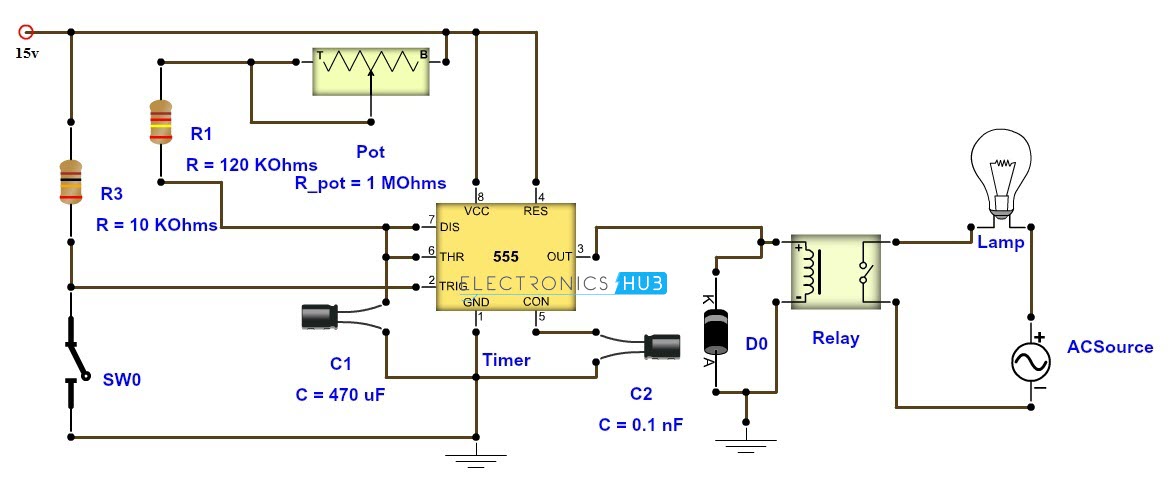
Adjustable Timer Circuit Diagram With Relay Output from www.electronicshub.org In setting the time period while a relay duly interfaced from the microcontroller operates the load as per the entry time for on period and off period is made. The circuit is designed to facilitate time adjustment of both charged and discharged states of the relay. The figures below show different schematics of simple timer circuits, which can be built very easily with few general components. This circuit has many applications on places where it is necessary to activate and deactivate (connect and disconnect) an electrical or electronic device. The output stays on for a few seconds and then turns off. December 26, 2017 at 3:16 am. Fixed delay on off timer circuit: When switch s1 is pressed then output will give high signal at pin 3 and transistor is on , therefore the connected load with relay is also switched on.
We have made a selection of themes based on mechatronics, are notes to basic topics are helpful to studies of automation and industrial design.
Fixed delay on off timer circuit: Off delay timer timing diagram. Normally closed time closed off delay contact (nctc) The main role in this circuit is played by the 555 timer ic. The simple delay timer circuit is similar and has just a few more components. In this circuit, we will show how to build a delay before turn on circuit with a 555 timer chip. There is a delay before the output turns on. A delay before turn on circuit is a circuit that once you apply power to it doesn't turn on the output right away. To set the time delay of our circuit we have used an electrolytic capacitor cx, if you want a time delay of a few seconds to use 10µf, for a delay of 2 minutes use 100µf and so on. Another point to note that you could use dc supply with this timer circuit. The use of timers in electrical and electronics is mainly focused on creating controlled delays in circuit operations. In this project we are going to design a simple time delay circuit using 555 timer ic.this circuit consists of 2 switches one for start the delay time and other for reset. Below you can see the schema.
Off delay timer timing diagram. A simple timer circuit can be built by using only a single or two transistors. Turn off after delay with mosfet. Once these few seconds pass, then the output. On delay timer and off delay timer:
Solved The Timing Diagram Shown Is That Of An 10 S Inpu Chegg Com from media.cheggcdn.com The main role in this circuit is played by the 555 timer ic. The important factor to remember when interpreting the off delay timing diagram is to remember that an off delay timer contains instantaneous contacts. In this post we discuss the making of simple delay timers using very ordinary components like transistors, capacitors and diodes. All these circuits will produce delay on or delay off time intervals at the output for a predetermined period, from a few seconds to many minutes. Below you can see the schema. This circuit has almost 10 to 12 seconds delay to turn on the load. Normally closed time closed off delay contact (nctc) You can use other mosfet too, but that should match your requirements.
We have made a selection of themes based on mechatronics, are notes to basic topics are helpful to studies of automation and industrial design.
Let's see how we can choose elements for the circuit, and how the delay depends on parameters of the elements. Since 1946 ise has been supplying timers, counters and controls to industry. This circuit uses very basic components like 555 timer and 4017 counter. Time off delay self latching circuit with zero current consumption during off state. Delay timer takes on hold the supply some moment and then starts to flow. At a certain time interval. The circuit is designed to facilitate time adjustment of both charged and discharged states of the relay. The circuit is pretty simple. On delay timer circuit diagram wiring diagram contactor with push button circuit diagram of delay timer on off power off delay timer circuit diagram 2 way lighting circuit triggering transformer push button fan switch light activated switch circuit diagram wd081 text. These circuits can be used for variety of timing purposes in electronic projects like time delay relay etc. In this circuit, we will show how to build a delay before turn on circuit with a 555 timer chip. It also has a potentiometer to adjust the time delay, where you can increase of decrease the time delay by just rotating the potentiometer. The below figure is the schematic of a simple automatic on off timer with a fixed timing resistor and capacitor.
Delay off timer circuit for off time delay , switch off delay timer. At a certain time interval. Fixed delay on off timer circuit: With the help of this circuit, a user controlled delay to relay can be given. Let's see how we can choose elements for the circuit, and how the delay depends on parameters of the elements.
Circuit Diagram For The Delay Timer Download Scientific Diagram from www.researchgate.net Here is a timer circuit using common ic 555. Using timers we can delay the circuit operation. Delay timer takes on hold the supply some moment and then starts to flow. The terminals are a good set of reference points. To set the time delay of our circuit we have used an electrolytic capacitor cx, if you want a time delay of a few seconds to use 10µf, for a delay of 2 minutes use 100µf and so on. The important factor to remember when interpreting the off delay timing diagram is to remember that an off delay timer contains instantaneous contacts. The below figure is the schematic of a simple automatic on off timer with a fixed timing resistor and capacitor. On delay timer and off delay timer:
On delay timer circuit diagram wiring diagram contactor with push button circuit diagram of delay timer on off power off delay timer circuit diagram 2 way lighting circuit triggering transformer push button fan switch light activated switch circuit diagram wd081 text.
Generally, timers are used to control the circuit for a certain amount of time. On/off delay timer circuits are simple electronic circuits that can either turn on or off a circuit after a predetermined time period has passed. The output stays on for a few seconds and then turns off. Each component should be placed and linked to other parts in particular manner. It only contains a transistor, a capacitor, several resistors, a switch and an led. In this circuit, we will show how to build a delay before turn off circuit with a 555 timer chip. It also has a potentiometer to adjust the time delay, where you can increase of decrease the time delay by just rotating the potentiometer. We have made a selection of themes based on mechatronics, are notes to basic topics are helpful to studies of automation and industrial design. These on off intervals can be adjusted by varying the 555 timer output and number of counter outputs. It means for some time output pin 3 is high and for some time it remains low, that will create a oscillating output. This time delay is set by the user. Either we can achieve a delay before the circuit turns on or we can turn off the circuit after a delay of some time period. Since 1946 ise is the preferred source for timers and controls for industry